 We’ll continue our introduction to the basics of car audio electrical theory by talking about wiring loads in series and parallel. Understanding the characteristics of each wiring option and how it relates to power delivery and current consumption is crucial in choosing the right speakers for your sound system. All reputable mobile enhancement retailers know the basics of series and parallel wiring by heart and can help you get the right combination of speakers or subwoofers to ensure optimum performance from your sound system.
Electrical Circuit Review
 At this point, you should be familiar with the basic concept of wiring a load to a power source. In our cars, this could be something as simple as plugging a USB phone charger into the center console or having your installer integrate an amplifier into the electrical system in your vehicle.
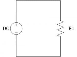
The most basic of electrical circuits has a single power source and a single load. The two devices are connected together with the positive terminal of the source connected to the positive terminal of the load and likewise for the negative terminals. Current flows from the power source, through the load and back to the opposite terminal of the source.
Wiring Loads in Parallel
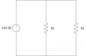
Any device we wire to the electrical system in our cars and trucks is considered to be wired in parallel with other loads. The positive connections all go to the same source of electricity, and the ground connections are all effectively connected to the same terminal of the battery.
The first and most important characteristic of loads wired in parallel is that the voltage across all of those loads is equal.
Knowing this makes it easy to calculate the current through each load using the equation I = V ÷ R. We can also calculate the power dissipated by each load using the equation P = V^2 ÷ R.
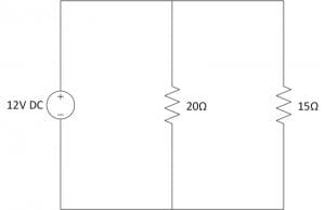
In the diagram above, we see two loads connected to a common 12-volt power source. Load 1 has a resistance of 20 ohms and Load 2 has a resistance of 15 ohms. Using the equations above, we can calculate that 0.6 amp of current flows though the 20-ohm load and 0.8 amp flows through the 15-ohm branch. Likewise, the 20-ohm branch dissipates 7.2 watts of energy and the 15-ohm branch dissipates 9.6 watts.
The power source needs to provide a total of 1.4 amps of current to the circuit.
Calculating the Resistance of Loads In Parallel
An important part of understanding parallel loads and how they affect the power drawn from the supply is a required understanding of how to calculate the net resistance of multiple loads in parallel.
The formula to calculate the total resistance multiple loads wired in parallel is 1/Rt = 1/R1 + 1/R2 + 1R3 and so on, until you have included all the loads.
For our 15- and 20-ohm loads in the example, the math would be: 1/Rt = 1/20 + 1/15, or 1/Rt = 0.05 + 0.06667. This works out to 1/Rt = 0.11667 which works out to 8.571 ohms.
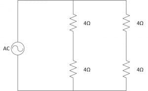
There are a few shortcuts you can take to calculate resistance when multiple loads of the same value are used. Look at the following circuit:
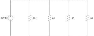
In this circuit, all four loads are 8 ohms. We can do the math and see that the net resistance is 2 ohms. Where all the loads in the circuit are the same, we can simply divide the resistance of each by the number of loads.
So, 1/8 + 1/8 + 1/8 + 1/8 = 8 ÷ 4 = 2
Please remember, this only works when all the load resistances are identical.
Wiring Loads in Series
The second option in terms of wiring loads together is to wire them in series. The schematic below shows two loads wired in series with a voltage source.
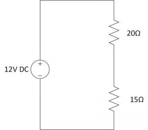
In a series circuit, the current through all the loads is the same. The voltage drop across the loads is dependent on the total current flowing in the circuit at the value of the individual load resistance.
Another trait of series circuits that makes them very easy to work with is that the total circuit resistance is equal to the sum of all the loads. The equation is Rt = R1 + R2 + R3 and so on until all the loads are considered. For our example with the 15- and 20-ohm resistors, the total resistance in a series circuit would be 35 ohms. The current through the circuit is calculated using the I = V ÷ R equation, which would be 12 ÷ 35, or 0.343 amp for this circuit.
To calculate the voltage across each load, we can multiply the current times the resistance for each value from the V = I x R equation. The voltage across R1 is 6.857 volts and the voltage across R2 is 5.143 volts. Not coincidentally, the sum of these two voltages is equal to our supply voltage of 12 V.
In automotive applications, the problem with wiring loads in series is that the total power supplied to the circuit depends on the resistance of each component in the circuit. This makes predicting results for dynamic loads very difficult. Where we do occasionally wire loads in series is when we connect subwoofers to an amplifier or in the rare occasion we are using passive crossover components with a speaker.
Series-Parallel Wiring for Subwoofers
 Let’s use the example of an amplifier designed to produce its rated power into a 4-ohm load. If we want to connect a single subwoofer to the amp, it should have a nominal impedance of 4 ohms. Depending on the brand of subwoofer you are looking at, you may have a single voice coil 4-ohm sub available, a dual 2-ohm configuration or a dual 8-ohm.
If you choose a dual 2-ohm woofer, the voice coils will need to be wired in series before the positive and negative connections are attached to the amplifier. If you use the dual 8-ohm sub, the coils need to be wired in parallel.
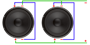
What if we want to wire multiple subwoofers to a single amplifier channel? In this case, the net impedance still needs to be 4 ohms. You can use a pair of single voice coil 2-ohm subs or a pair of dual 4-ohm subs. The pair of 2-ohm subs would be wired in series and then to the amp. The dual 4-ohm subs would have their individual voice coils wired in series, then the two subwoofers would be wired in parallel to the amplifier.
You will note that we switched the power source in this diagram to an AC source. You can think of that as your amplifier. We didn’t want anyone calling us out for suggesting that you connect your subwoofers to your battery.
You can continue wiring multiple subwoofers in simultaneous series and parallel loads until you run out of trunk space, so long as the net results keeps the amp happy with a 4-ohm load.
Choose the Right Subwoofers for Your Amplifier
Understanding the basics of series and parallel wiring is instrumental in ensuring you get the right subwoofer combination for your amplifier, or the right amplifier for your choice of subwoofers. Your local mobile electronics specialist retailer can help ensure you get the right solution for your application and install it so that it sounds great. In the next car audio electrical theory article, we will introduce the concept of alternating current.
This article is written and produced by the team at www.BestCarAudio.com. Reproduction or use of any kind is prohibited without the express written permission of 1sixty8 media.
Leave a Reply